OPX+ Installation Guide
The following page describes the installation procedure of a single OPX+, a multi-OPX+ in an OPT topology, and for systems with Octaves. It covers network configuration, OPX+ connectivity, rack scheme and more.
Cluster
A cluster is a synced and fully-connected system of OPX+ controllers, Octaves, OPTs, and other QM devices. A cluster can be comprised of a single OPX+, it can have multiple OPX+ (and for that, OPTs), and it may or may not include Octaves. For each cluster, there is a main OPX+ and, in the case of a multi-OPX system, secondary OPXs.
The cluster can be managed and configured via a web admin panel. Through the admin panel, one can check the cluster's health status and topology, restart the cluster, configure clock settings, access logs, and more. As detailed below, multiple clusters can exist in the same network and be managed by the web admin panel.
Hardware Installation Procedure
-
Verify you have all of the required components.
-
Mount the system:
Mount the OPX+ and the router in a rack or on a shelf.
Place the OPX+ controllers and the OPT in the rack according to the rack scheme.
-
Determine your network configuration.
-
Connect the system:
- Connect the OPX+ to the power.
- Optional: Connect the OPX to an external reference clock.
- Connect the OPX+ to port 2 of the router.
- Connect the OPX+ clock input to the Octave clock output via an SMA cable.
- Optional: Connect the Octave to an external reference clock.
- Connect the OPX+ and octave to the power.
- Connect the OPX+ and octave to ports 2 & 3 of the router.
Up to 6 devices - OPX+es and Octaves.
Connect the cables according to the connectivity scheme, in the following order:
- Connect the OPX+ and Octaves to the clock distributed from the OPT via an SMA cable.
- Connect the USB from the OPT to any USB port of the main OPX+.
- Optional: Connect the OPT to an external reference clock.
- Connect the OPX+ controllers via a SMA cable with a DC block to form a chain, as specified in the
clock & syncsection of the connectivity scheme. - Connect the optical cables used for data sharing between controllers. Remove the connectors' protectors if present.
- Connect the OPX+ and Octaves to the router via the ethernet cables, starting from port 2 onwards.
- Connect the OPX+, Octaves and the OPT to the power outlet.
More than 6 devices - OPX+es and Octaves
- Use one OPT as a main OPT, connecting all other OPTs' Clk In to the main OPT clock outputs.
- Connect the USB from the main OPT to any USB port of the main OPX+.
- Connect the USB from the other OPTs to any USB port of other OPX+es.
- Optional: Connect the main OPT to an external reference clock.
- Connect the OPX+ and Octaves to the clock distributed from the OPTs via an SMA cable.
- Connect the OPX+ controllers via an SMA cable with a DC block to form a chain, connecting AUX i from one controller to another controller's AUX i (for i=1,2), as depicted in the Qsync connectivity below.
- Connect the optical cables used for data sharing between controllers. Remove the connectors' protectors if present.
- Connect the OPX+ and Octaves to the router via the ethernet cables, starting from port 2 onwards.
- Connect the OPX+, Octaves and the OPTes to the power outlet.
-
Turn on all the devices.
- When using new devices, configure the cluster, as shown below. This step can take ~30 minutes.
- Once clustered, the system will start calibrations, and the boot sequence should take a few minutes.
-
Open a browser and type the system's IP in the address field to access the admin panel where you can configure the system, check its status and more. See the network overview section below for more details on how to access the cluster
-
Install the latest Python package by typing
pip install --upgrade qm-quain the desired Python environment. - Open a communication in Python using:
This requires passing the correct arguments to the QuantumMachinesManager object. See "accessing the cluster" options below.
You should see the message
qm - INFO - Health check passedin the console.
Network Overview and Configuration
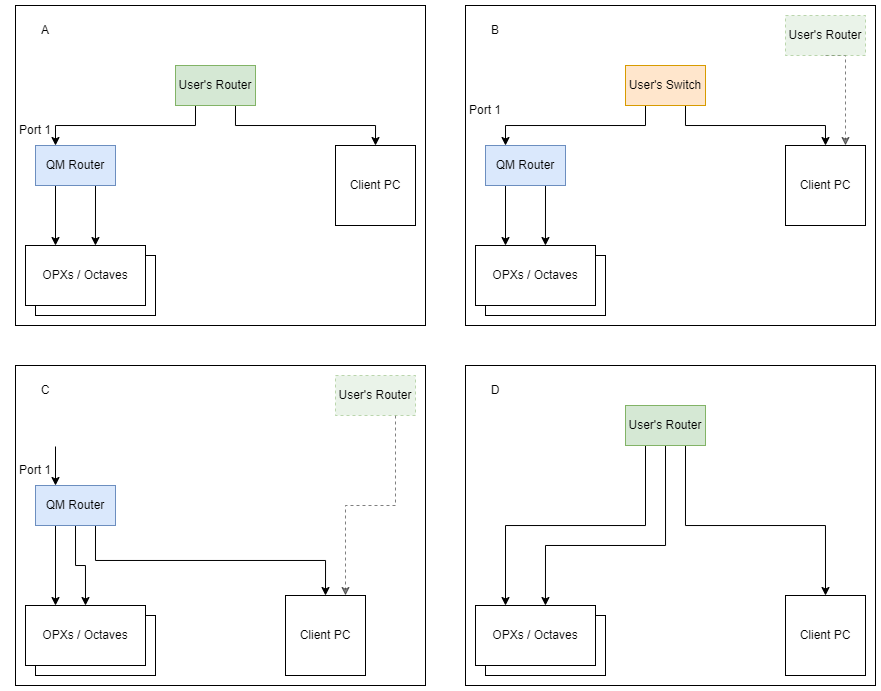
As a recommendation, we ship the OPX+ & Octave system with an external router for network management (hereafter, the QM router). There are a few possible network configurations, and each modifies how we access the cluster. We list below four possible configurations and details on accessing the cluster. Please choose your relevant configuration by clicking on the tabs under the figure.
Note
If you plan to connect the system to your local network, please check if it requires whitelisting the MAC address. Depending on the configuration below, you might need to whitelist the supplied router MAC address or the individual devices' MAC addresses. All QM devices have their MAC address printed on them. To find the QM router MAC address, follow the guide below or contact your QM representative.
In this scenario, both the QM router and the client PC are connected to the institute's network, with the QM router listed as a device on the network. All QM devices are in a local area network (LAN) behind the QM router.
Network Setup:
-
If necessary, ensure the QM router is whitelisted with the institution's IT department.
-
Connect the QM router to the network through port 1. By default, it will be assigned an IP through DHCP (Automatic). If a static IP is required, the IT department at the institution needs to provide it. More information on configuring the QM router can be found here.
Accessing the web admin and connecting to the cluster using Python can be done in the following way:
There is one web admin panel for all devices and clusters that is accessible by typing the IP address of the QM router in a web browser. If you are unsure what is the QM router's IP address is, see here. Moreover, all clusters behind the router must have the same version for the admin panel to control them.
To open a communication with the cluster in Python, use the following with the name of the cluster, as defined in the admin panel.
There is one cluster per router, and the web admin panel is available by typing in the IP address of the QM router in a web browser. If you are unsure what is the QM router's IP address is, see here.
To open a communication with the cluster in Python, use the following:
In this scenario the QM router and the client PC are connected to a local unmanaged switch. All QM devices are in a local area network (LAN) behind the QM router.
Network Setup:
-
Connect the QM router to the switch through port one .
-
Set the QM router's IP to a static one, as required by the switch's LAN. Instructions can be found here.
Accessing the web admin and connecting to the cluster using Python can be done in the following way:
There is one web admin panel for all devices and clusters that is accessible by typing the IP address of the QM router in a web browser. If you are unsure what is the QM router's IP address is, see here. Moreover, all clusters behind the router must have the same version for the admin panel to control them.
To open a communication with the cluster in Python, use the following with the name of the cluster, as defined in the admin panel.
There is one cluster per router, and the web admin panel is available by typing in the IP address of the QM router in a web browser. If you are unsure what is the QM router's IP address is, see here.
To open a communication with the cluster in Python, use the following:
In this scenario, the client PC is directly connected to the QM router.
The QM devices and the PC are in a local area network (LAN) behind the QM router.
Network Setup:
-
Ensure that port 1 is unused on the QM router.
-
Connect the other ports to the PC and QM devices.
Note
If your PC is connected to another network (e.g., for internet) with a proxy server, this may result in conflicts and may require excluding the QM router network (192.168.88.xxx) from the proxy. To accomplish this, we suggest asking for assistance from the institution's IT personnel or contacting us. It is recommended to set all QM devices (e.g., OPXes and Octaves) to static IP addresses.
Accessing the web admin and connecting to the cluster using Python can be done in the following way:
To access the web admin panel, type any device's IP in a web browser to access all clusters using the same QOP version. To find the IP of the devices connected, follow the steps below
To open a communication with the cluster in Python, use the following:
Warning
This option is only officially supported from
In this scenario, the QM router is unused, and all QM devices will be directly connected to your own network (typically a router).
Note
All QM devices shipped after June 2023 are configured to DHCP. Devices shipped before were configured with a static IP - 192.168.88.XXX.
Network Setup:
- Determine the IP requirements of your network, and set the devices' IPs accordingly. Contact QM support for assistance with changing IP addresses. If a static IP is required, it must be provided by the institution's IT department. Note that this frequently requires whitelisting the MAC addresses of all QM devices in advance.
Accessing the web admin and connecting to the cluster using Python can be done in the following way:
To access the web admin panel, type any device's IP in a web browser to access all clusters using the same QOP version. To find the IP of the devices connected, follow the steps below
To open a communication with the cluster in Python, use the following:
Extra Topics
Required components
List of Components
To ensure a smooth installation, please make sure you have the following components:
| Component name | Quantity | Notes |
|---|---|---|
| OPX+ controllers | \(N_{opx+}\) | nan |
| OPX Power cables | \(N_{opx+}\) | nan |
| Router | 1 | Supplied by QM, with at least \(N_{opx+}+1\) ports |
| Ethernet cables | \(1 + N_{opx+}\) | nan |
| Router power supply | 1 | nan |
| SMA cables | \(2 * N_{opx+} - 1\) | Only for a Multi-OPX+ system, Identical Cables |
| DC Blocks | $ N_{opx+} - 1$ | Only for a Multi-OPX+ system, Identical Cables |
| Optical cables | \(6 * N_{opx+}\) | Only for a Multi-OPX+ system |
| OPT | 1 | Only for a Multi-OPX+ system |
| OPT Power cables | 1 | Only for a Multi-OPX+ system |
| USB cable (OPT to main OPX+) | 1 | Only for a Multi-OPX+ system |
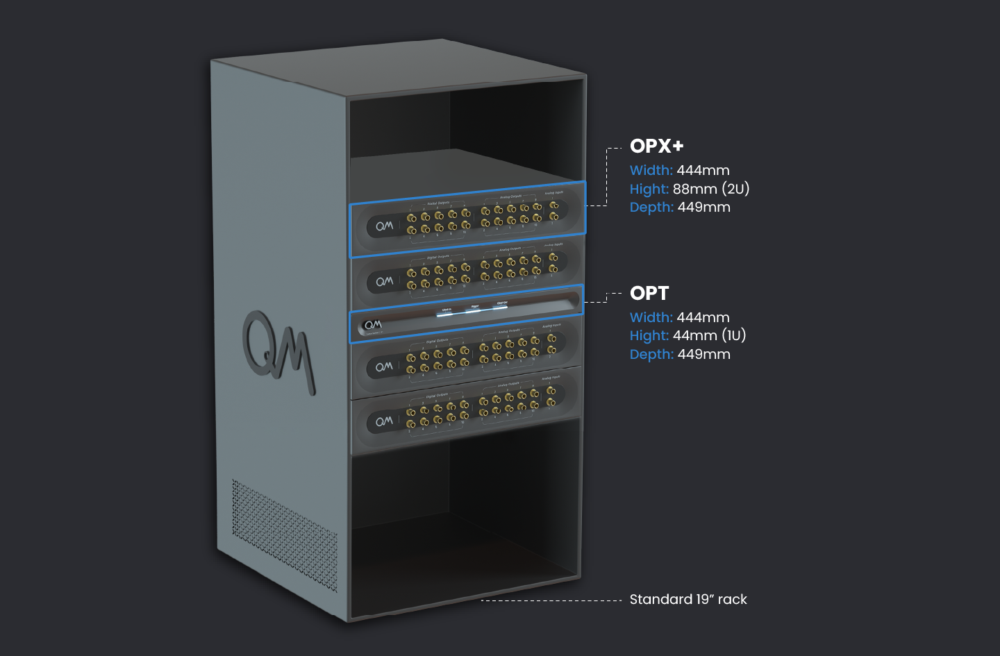
Rack Scheme
Rack scheme
The system fits a standard 19" rack. The sizes of the controllers are shown in the image below. The controllers can be mounted to the rack with the supplied adaptors or stacked on a shelf. The router can be rack-mounted at the back of the rack or simply stacked. For a system of more than 2 OPX+ controllers, it is recommended to place the OPT in the center of the stack, such that equal-length cables will reach all controllers.
The image below demonstrates the preferable OPX+ controllers and OPT placement for a system of 4 controllers.
Connectivity Scheme
The multi OPX+ system has four required connectivity groups. Clock & sync, Inter-controller communication, Network and Power
Clock & sync
The clock signal is distributed by the OPT with an SMA cable per controller. An inner/outer DC block is optional and can be added to reduce ground loops. In addition, the main OPX+ of the cluster connects to the OPT via USB, to any of the 2 USB ports of the OPX+.
A sync signal is passed between the controllers via SMA cables between the AUX ports. The connectivity should alternate between AUX1 (1.8V) to AUX1 (1.8V), and AUX2 (1.8V) to AUX2 (1.8V), as seen in the picture. An inner/outer DC block (supplied) is required to avoid potential damage to the devices and to reduce ground loops.
Note
In some back panels, the labels are different. AUX1 is AUX2, and AUX2 is AUX3. The location of the port is the same as in the picture above.
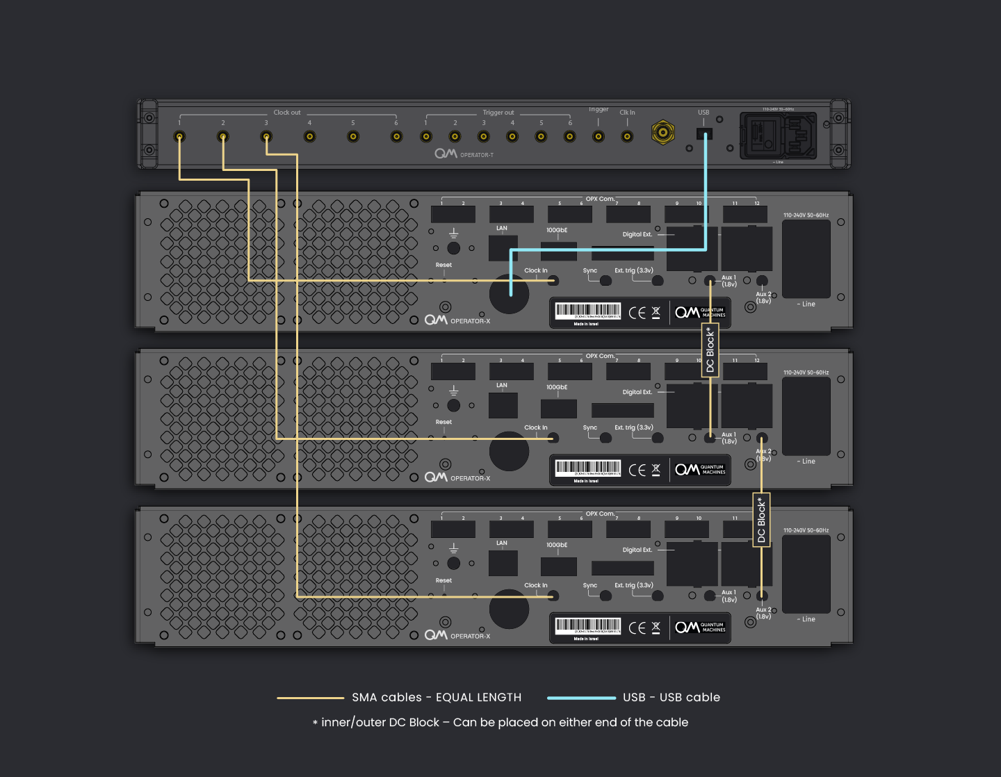
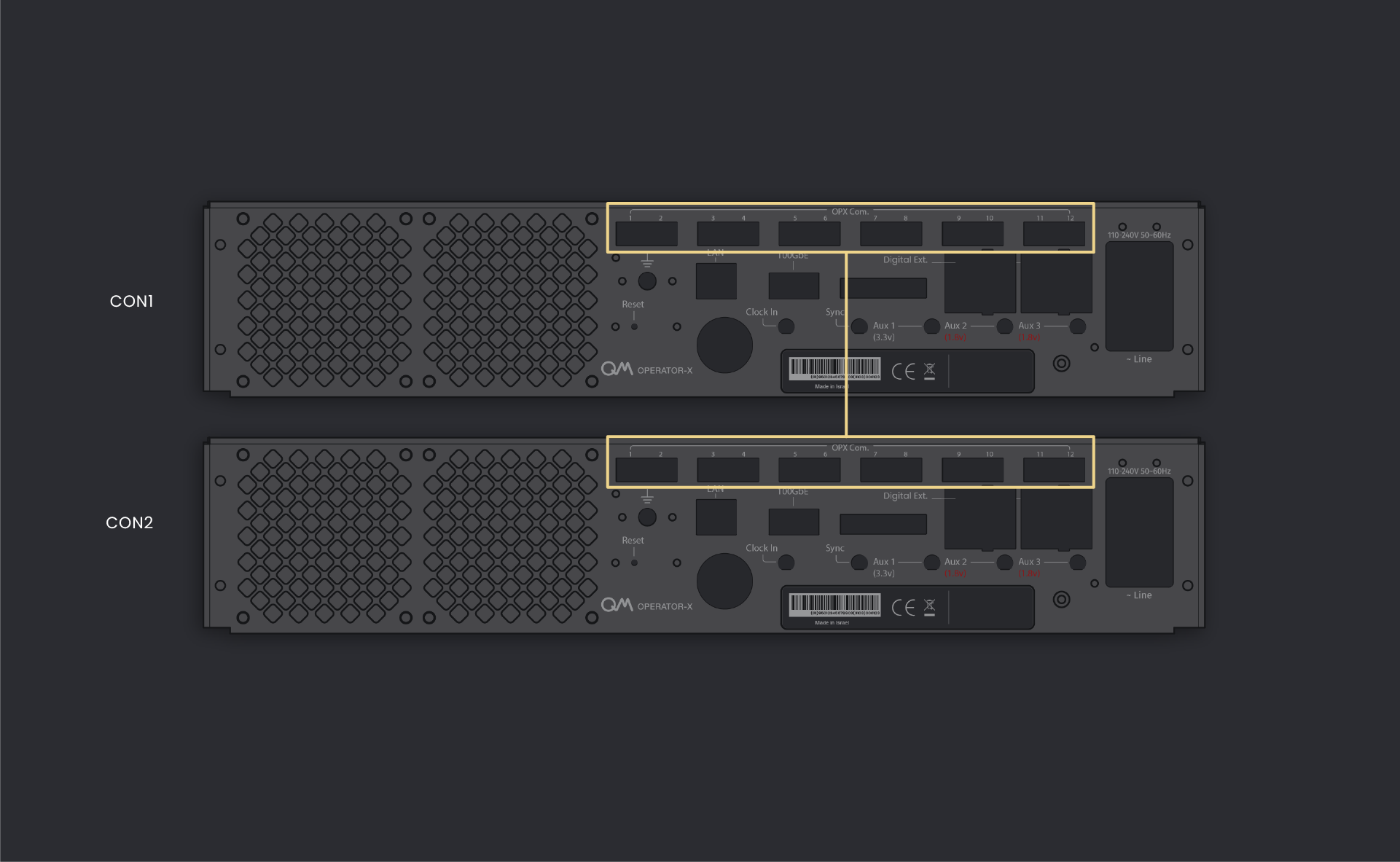
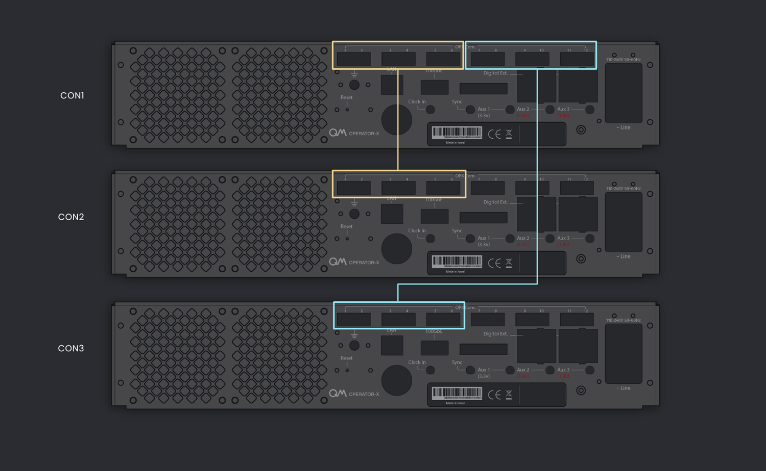
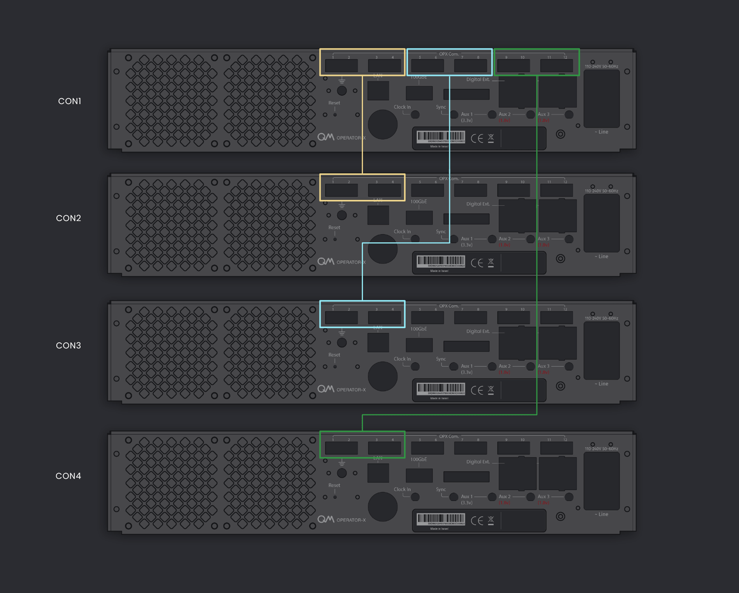
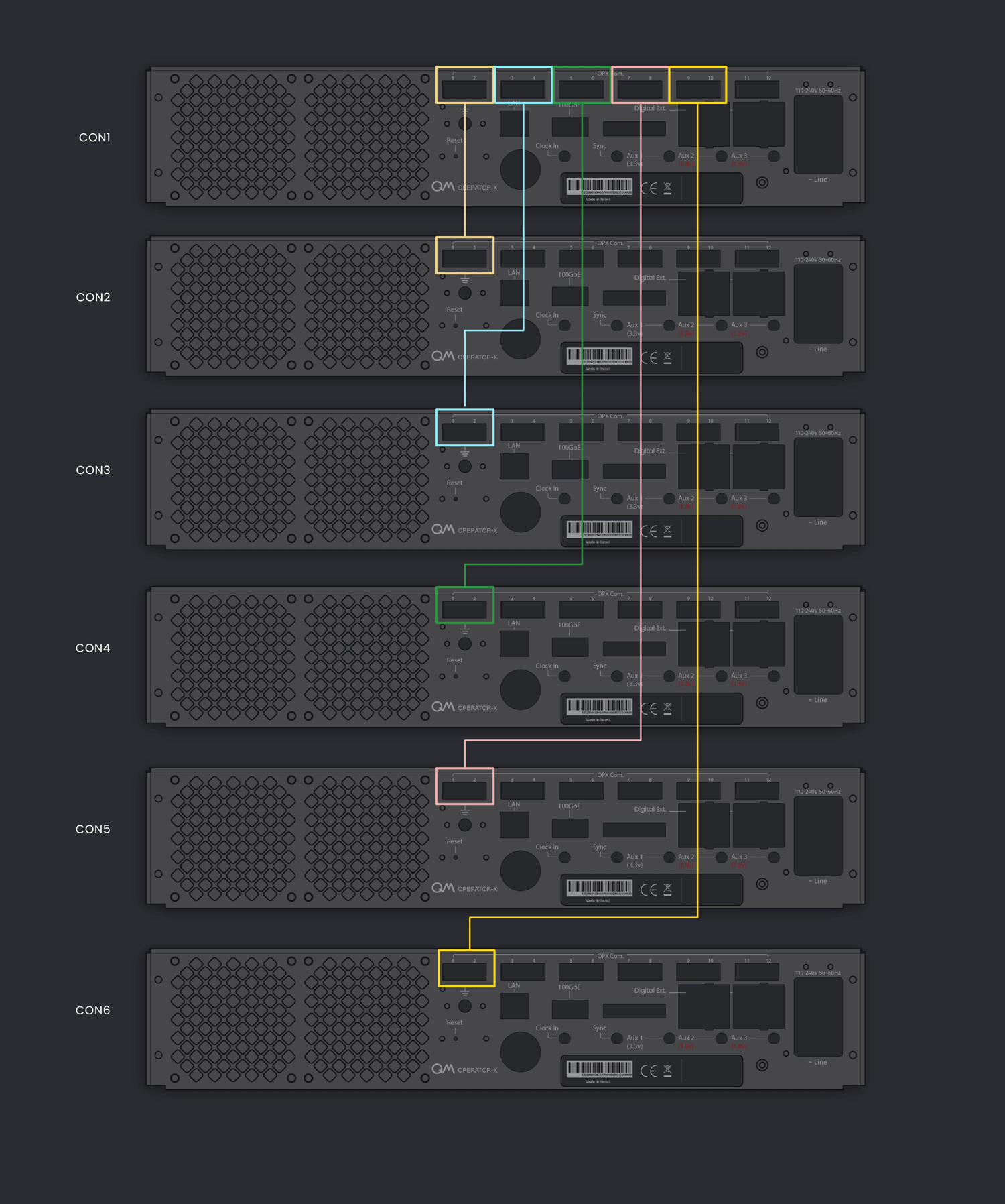
Inter-controller Optical Connectivity Scheme
Data transfer and communication between controllers are operated via optical cables in an all-to-all connectivity.
Each OPX+ has 12 optical ports and the preferred connectivity configuration differs with the number of
controllers, as shown in the animations below.
Click on each configuration to see the preferred connectivity scheme.
Note
The following is only a recommendation. Every configuration that establishes all-to-all connectivity is valid.

Configuring OPX+ & Octave
Check Devices IP
- Connect the devices and a computer to the local network of the QM router (ports 2-10)
- In CMD run:
- Identify the IP of the device using its MAC addresses. The MAC address is printed on a sticker on the device.
Configuring the Device's IP
It is possible to change the IP of the devices. If it is needed, please contact QM for assistance.
Cluster Devices
Follow the steps in this video
Configuring the QM router
Configuring the router to static IP
If static IP is needed for your system, follow these steps:
- Connect a computer to the router (to any port 2-10).
- Connect to the router web interface by typing in the browser
http://192.168.88.1:81 - Click cancel in the change password dialog.
- Click "Quick Set" at the top banner.
- Set up the Static IP:
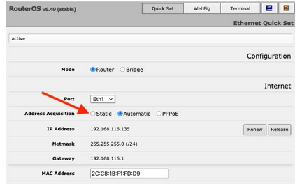
- Click "apply configuration" to save changes.
- Disconnect the computer from the router.
Note
The router's IP and MAC addresses can also be seen on this page.
- Connect a computer to the router (to any port 2-10).
- Connect to the router web interface by typing in the browser
http://192.168.88.1 - Click cancel in the change password dialog.
- Click "Quick Set" at the top banner.
- Set up the Static IP:
- Click "apply configuration" to save changes.
- Disconnect the computer from the router.
Note
The router's IP and MAC addresses can also be seen on this page.
View the router's IP and MAC addresses
Use the touch screen on the router's front panel to view information and optional configuration. At any stage you can click back and return to the previous screen.
-
Click on "Interfaces" once
-
Click on "ether1"
-
To view the IP address press "Addresses" and to view the MAC address press "Info"