External Clock
When we want to synchronize two or more OPX modules to one clock or use a clock other than the internal one, we may use an external clock source. Here we discuss the different ways to connect, distribute and configure external clock as well as its characteristics and limitations.
Octave's External Clock
For the Octave's external clock please see the Octave guide
QOP External Clock Input Characteristics
The QOP can receive an external clock at three frequencies: 10, 100, and 1000MHz (1GHz). The clock input impedance must be 50Ω. The 10 or 100 MHz clock must have its peak-to-peak voltage be between 0.35 to 2.3 V (-5 to 11 dBm). The 1000 MHz clock must have its peak-to-peak voltage be between 0.45 to 1.25 V (-3 to 6 dBm).
Note
The external clock input is AC coupled
OPT External Clock Characteristics
The OPT distributes clocks across up to six systems. In addition, multiple OPTs can be chained to distribute clocks to more systems.
It distributes a 1 GHz clock across devices. In the , it also synchronizes the connected systems.
Let's define what they are and what are the optimal ranges of the for the OPT:
- Jitter is the timing variations of a set of signal edges from their ideal values. Jitters in clock signals are typically caused by noise or other disturbances in the system. Contributing factors include thermal noise, power supply variations, loading conditions, device noise, and interference from nearby circuits. The OPT output jitter is less than 100fs.
- Skew is a phenomenon in digital circuits where the same clock signal arrives at different components at different times due to gate or wire signal propagation delay. The instantaneous difference between the readings of any two clocks is called their skew. Skew can be caused by many different things, such as wire-interconnect length, temperature variations, variation in intermediate devices, capacitive coupling, material imperfections, and differences in input capacitance on the clock inputs of devices using the clock. As the clock rate of a circuit increases, timing becomes more critical, and less variation can be tolerated for the circuit to function correctly. The OPT skew between clocks is smaller than 20ps.
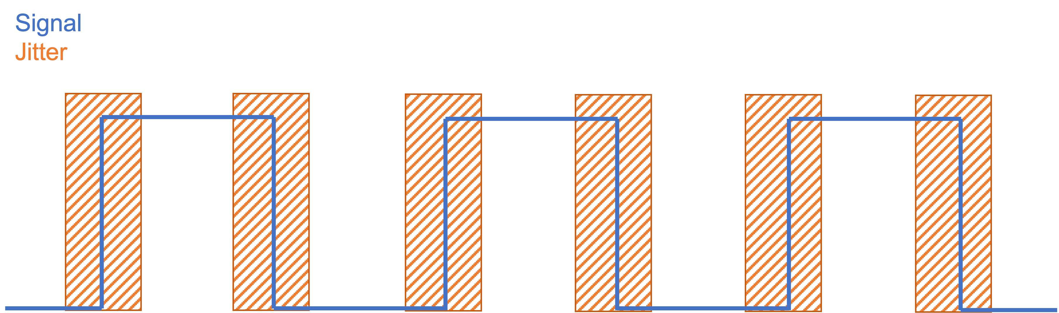
OPT Clock Output
| Symbol | Max | Units |
|---|---|---|
| Jitter | 100 | fs |
| Skew | 20 | ps |
Connectivity
Note
This is for a single OPX, for multiple OPXes, please connect your external clock to the OPT.
Connect your clock output to the 'External Clock' port on the back panel of the OPX:
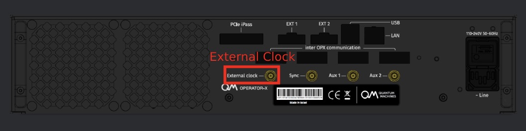
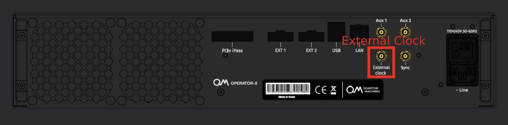
Some OPX back panels are slightly different, the connectivity then is as follows:
Important
Some early back panels might have different labels. However, the correct labels are the ones shown on this page.
Note
This is for a single OPX+, for multiple OPX+es, please connect your external clock to the OPT.
Connect your clock output to the 'Clock in' port on the back panel of the OPX+:
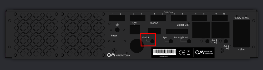
Connect your clock output to the 'Clk In' port on the back panel of the OPT.

Clock Configuration
Access your OPX admin panel through the browser. On the settings page, you can see radio buttons to choose between internal and external clock.
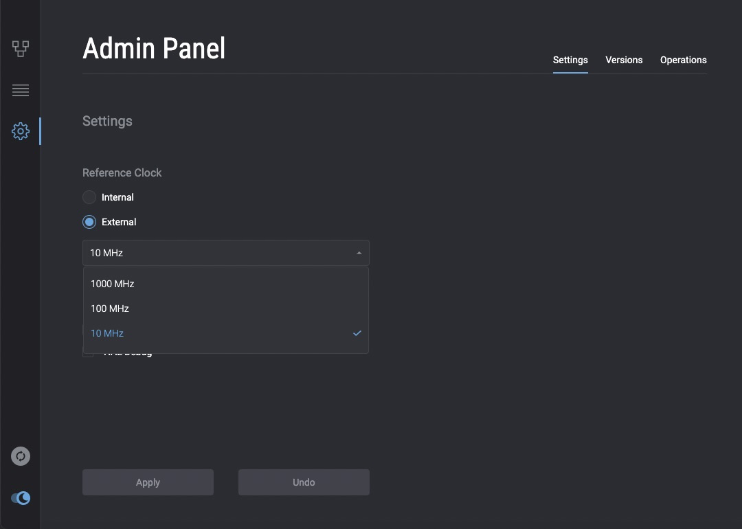
After the frequency was chosen, click apply and wait for the system to restart with the new clock.

Important
Changing the clock frequency will result in a system reboot
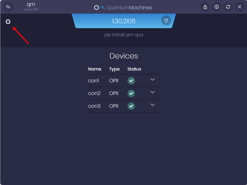
Log in to your OPX through the QMApp. On the main window you will see all the OPXes in that cluster. Press on the settings icon to go into the clock settings.
Pick a clock frequency and press apply. Now you can either restart the OPX for the change to occur immediately or restart later and continue working with the current clock configuration.
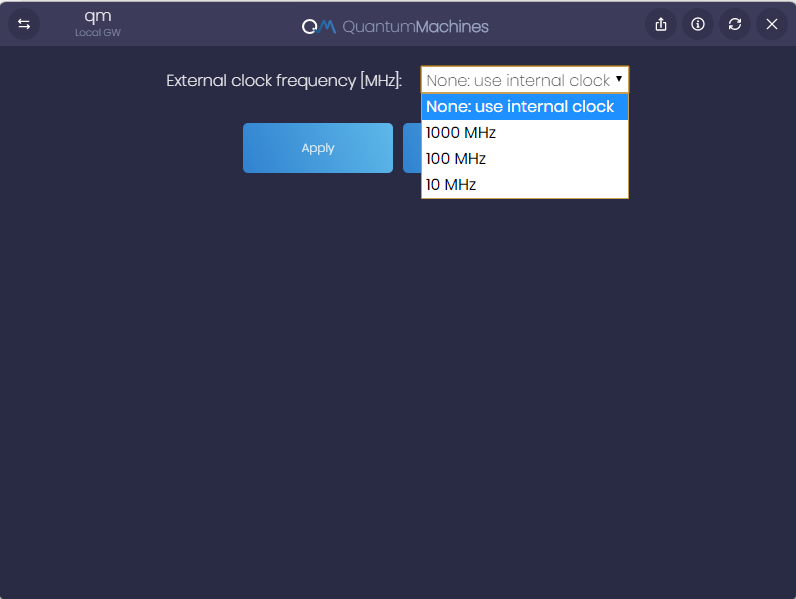
Important
Changing clock frequency will result in a system reboot